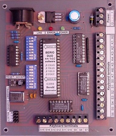
BERIO DUO
Intelligent MIDI interface for two-manual organ systems.
The Berio DUO module is microcomputer system, which is able to connect your two keyboards or another similar musical instrument to your musical electronic system equipped with MIDI interface. Thanks to built-in MIDI module, keyboards acquire sound. Keyboards or other instruments may then be connected to electronic sound module, electronic keyboard or to a PC, which can play your performace real-time.
Technical characteristics:
Input data
- input data for Berio DUO modules are signal from contacts of keyboard keys or whatever keypad providing contact of your choice. Berio DUO system is able to serve up to 2 x 64 keypad contacts in two manuals. Keyboard state is scanned in time multiplex way. This means that keyboard with both manuals (128 switches) may be connected to Berio DUO via 24 wires only. But it's necessary to connect one cheap small diode under each keypad. Diode and keypad wiring is described on diode matrix diagram below (see supplement). All wires on Berio DUO board are terminated by screw-connector.
Output data
- as output data, standard MIDI signal is generated. System board is equipped with standard 5-pin DIN connector MIDI OUT, which may be connected via standard MIDI cable to a personal computer or electronic keyboard with MIDI IN input. Standard MIDI cable schematic is drawn below (see supplement).
MIDI channel setting
- system is able to transmit MIDI data on two independent MIDI channels. One of selected channels is used for the first manual and other channel is used for the second manual. MIDI channel select is provided by miniature DIP switches located on system board. Meaning of DIP settings is described in the table (see supplement). Changes in DIP setting are accepted every time when all keypads and both pedals Sustain are released.
Transposition setting
- system is able to transpose generated MIDI data over eight entire octaves, lowest keypad sound is always "C" note. Transposition feature is possible for each manual independently. Transposition value is selected by miniature DIP switches located on system board. Meaning of DIP settings is described in the table (see supplement). Changes in DIP's setting are accepted by system every time when all keypads and both pedals Sustain are released.
Velocity setting
- Berio DUO system is intended to use in organ systems where velocity is not sensed, therefore velocity level in transmitted MIDI data is fixed to "forte" level (in compliance with MMA recommendations).
Indication LEDs
- system is equipped with three indication LEDs:
Power supply
- system board is powered by DC voltage 8 up to 18 Volts. Supply current is approx. 50 mA, voltage polarity must be respected. Regular power supply adapter for 230V/50Hz may be used (no special requirements). Recommended output rating of power supply adaptor is 9 V/300 mA.
Input Digital Filtering
- for better performance, the Input Digital Filtering unit is implemented in the system. This unit should eliminate the surges on keypad contacts. Keyboard state is read periodically in approx. one-millisecond intervals. State of every keypad must be repeatedly read as unchanged. Only then a MIDI message is generated. Pedals Sustain state is filtered by the same way.
Unlimited polyphony
- Berio DUO system does not restrict polyphony in any way. It means that if, in theory, all keys on both keyboards are pressed simultaneously, all corresponding data will be sent on the MIDI line.
Demonstration song
- if three lowest keypads on manual A are pressed during system start up, Berio module plays short demonstration song. While it plays, red LED Error comes on. When demo song has finished, LED Error is goes off and system begins normal operation.
Diode matrix
- diode matrix should be implemented near keyboard contacts. Matrix wiring is shown in schematic (see supplement).
Damper / Sustain pedals (foot switch)
- two pedal (foot switches) can be connected to system Berio DUO, interpreted as Damper / Sustain. This two pedals are connected via keyboard diode matrix as the highest keypad on each manual (alternative function of highest keypad).
ESD protection
- system is based on the High Speed CMOS technology (Complementary Metal-Oxide Semiconductor). Protection against damages due to electrostatic discharges is assured by clamp diodes on all terminals for keyboard.
Generated code compatibility
- MIDI code generated by Berio DUO system is compatible with any device made by the following manufacturers:
Installation recommendations
- wire length between keypad contact and Berio DUO system board should be as short as possible. The wires must not be grounded, connected to power supply or connected to each other.
In case, when number of connected keypads is smaller than nominal Berio module keypad number, keypad contacts should be connected in order from the lowest keypad to higher keypads. Some highest keypad positions then remains unconnected. Berio DUO module detects automatically, which keypads are wired and which are not.
Manufactured system standard features
- Berio DUO module is produced in only one configuration. It can serve up to 2 x 64 keypads in two manuals. Each manual can generate MIDI data in different channel. Transposition may be set over eight entire octaves independently for each manual. Highest keypad in each manual are interpreted as pedal Sustain. Power supply: 8..18 V DC.
Mechanical data
Guarantee: 2 years (24 months)
Supplement, additional information, download:
MIDI channel select table.
Transposition select table.
Berio DUO - Diode matrix schematic and connection of matrix to system board.
Berio DUO - Description, installation instructions and user manual for download (PDF format).
Standard MIDI cable schematic.
Basic electrical specification of MIDI.
Recommended connection of standard MIDI cable to sound card "gameport".
FAQ - Frequently asked questions with answers.
© 1998-2025 AkordeonCentrum.cz