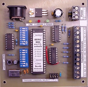
The BERIO MIDI 32
Intelligent MIDI interface for organ pedal-boards.
The Berio MIDI 32 module is microcomputer system, which is able to connect your organ pedalboard or another musical instrument to your musical electronic system equipped with MIDI interface. Thanks to built-in MIDI module, pedalboard acquires sound. Pedalboard or other instrument may then be connected to electronic sound module, electronic keyboard or to a PC, which can play your performace real-time.
Technical characteristics:
Input data
- input data for Berio MIDI 32 modules are signal from contacts of pedalboard keys or whatever keypad providing contact of your choice. Berio MIDI 32 module is able to serve up to 32 pedal contacts. Keypads state is scanned in time multiplex way. This means that keyboard with 32 keys may be connected to Berio module via 12 wires only. But one cheap small diode must be connected under each keypad. Diode and keypad wiring is described in diode matrix schematic (see supplement). All wires on the Berio module board are terminated by screw-connector.
Output data
- as output data, standard MIDI signal is generated. System board is equipped with standard 5-pin DIN connector MIDI OUT, which may be connected via standard MIDI cable to a personal computer or electronic keyboard with MIDI IN input. Standard MIDI cable schematic wiring is drawn in the supplement below.
MIDI channel setting
- system is able to generate MIDI data on any one or two MIDI channels simultaneously. Basic MIDI channel number is set by four jumpers placed on the system board. Additional channel may be set by DIP switch "Control" on the system board. Data generation on the additional MIDI channel may be enabled or disabled by the "Control" DIP switch too. Position meaning of jumper caps and DIP switches are described in MIDI Channel Jumpers Position Table and "Control" DIP switches function (see supplement below). Changes in jumper or DIP settings are accepted every time system is restarted or powered up.
Note: What is the reason for the same data generating at two MIDI channels simultaneously?
Most of electronic organ-type musical instruments have assigned one voice to one MIDI channel. When you need play with more than one voice, you need the same data generated in more MIDI channels. With this feature, data from Berio MIDI 32 pedalboard module may be interpreted e.g. by "General" and "Bass" voices at the same time.
Example: Some electronic organ mfr. Viscount (e.g. Cantorum series) plays data received at channel 1 by "General" voice (basic voice, right hand) and data received at channel 4 by "Bass" voice (bass, left hand). Therefore Berio MIDI 32 module in pedalboard may sound by "General" or by "Bass" or by "General" and "Bass" simultaneously (when two-channel mode applied).
Enable and disable of MIDI channels at play
- generating of MIDI data may be permanently enabled or disabled via one of "Control" switches. If you need to enable or disable individual MIDI channel at play (it means e.g. enable or disable individual voices), "Control" switch nr. 7 must be turned into "ON" position. In this case, two highest keypads (usually not wired, not used) works as individual MIDI channel enable switches. More detailed function is described in the table (see supplement below).
Transposition setting
- system is able to transpose all generated MIDI data. Transposition may be performed over entire range of audible tones or, more precisely, over all tones supported by MIDI protocol. Transposition value is selected by seven miniature DIP switches located on the system board. Meaning of DIP settings is described in the table (see supplement below). DIP's setting is accepted by system every time the system is restarted or powered up.
Velocity setting
- system is able to generate MIDI data with one of two velocity levels: "forte" (MIDI nr. 64, recommended value) or "forte fortissimo" (MIDI nr. 127, max. value). Used velocity level is selected by one of "Control" switches. For detailed description see table (see supplement below).
Indication LEDs
- system is equipped with three indication LEDs:
Reset/Accept button
- Berio MIDI module is equipped with Reset/Accept push button. This button may be used for acceptance of new DIP switches or jumpers setting. In normal action, this button needn't be used - acceptance is provided automatically after power-up.
Power supply
- system board is powered by DC voltage 8 up to 18 Volts. Supply current is approx. 50 mA, voltage polarity must be respected. Regular power supply adaptor for 230V/50Hz may be used (no special requirements). Recommended output rating of power supply adaptor is 9 V/300 mA.
Input Digital Filtering
- for better performance, the Input Digital Filtering unit is implemented in the system. This unit should eliminate the surges on keypad contacts. Keyboard state is read periodically in approx. one-millisecond intervals. State of every keypad must be repeatedly read as unchanged. Only then a MIDI message is generated.
Unlimited polyphony
- Berio MIDI system does not restrict polyphony in any way. It means that if, in theory, all pedals on pedalboard are pressed simultaneously, all corresponding data will be sent to MIDI line.
Demonstration song
- if three lowest keypads are pressed during system reset or start up, Berio module plays short demonstration song. While it plays, red LED Error comes on. When demo song has finished, LED Error is goes off and system begins normal operation.
Diode matrix
- diode matrix should be implemented near keyboard contacts. Matrix wiring is shown in schematic (see supplement).
ESD protection
- system is based on the High Speed CMOS technology (Complementary Metal-Oxide Semiconductor). Protection against damages due to electrostatic discharges is assured by integrated clamp diodes on all terminals for keyboard.
MIDI code compatibility
- MIDI code generated by Berio MIDI system is compatible with any device made by the following manufacturers:
Installation recommendations
- wire length between keypad contact and Berio MIDI system board should be as short as possible. The wires must not be grounded, connected to power supply or connected to each other.
In case, when number of connected keypads is smaller than nominal Berio module keypad number, keypad contacts should be connected in order from lowest keypad to higher keypads. Some highest keypad positions then remains unconnected. Berio MIDI module detects automatically, which keypads are wired and which are not.
Manufactured system standard features:
Mechanical data
Guarantee: 2 years (24 months)
Supplement, additional information, download:
Basic MIDI channel select jumpers setting table.
Transposition DIP position table.
"Control" DIP switches function.
Berio MIDI 32 - Diode matrix schematic and connection of matrix to system board..
Berio MIDI 32 - Description, installation instructions and user manual for download (PDF format).
Standard MIDI cable schematic.
Basic electrical specification of MIDI.
Recommended connection of standard MIDI cable to sound card "gameport".
FAQ - Frequently asked questions with answers.
My home organ. (In English and Slovak language.)
Original home organ construction. Detailed description of pedalboard switching system (reed sensor type).
Website is not available? See local copy of website here.
How to build a complete church organ at home. (In Czech only.)
Detailed description of organ construction with photos (including pedalboard, prices etc.).
Website is not available? See local copy of website here.
© 1998-2025 AkordeonCentrum.cz